Nortek global hvacreznor does not endorse any field changes to factory wiring schemes. Wiring color codes here is a listing of common color codes for evinrude and johnson outboard motors.
Mounting and wiring variable air volume modular assembly vma 1400 series controllers technical bulletin 8 when using a single transformer to power multiple vmas use a wire gauge large enough to handle the current and minimize the voltage drop.

You can find out more Diagram below
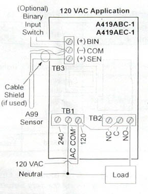
Johnson control wiring diagram. Outboard wiring diagrams these diagrams are accurate to the best of our knowledge. Refer to figures 3 through 7 for wiring diagrams. Easy access to the terminals is desired for wiring and servicing.
However variations can exist such as between remote control and tiller models. These codes apply to later model motors approximately early 80s to present. Also note that certain field modifications may occur to accommodate the use of other control systems.
Choose a location that provides the shortest direct cable route to the spark electrodeflame sensor assembly. All servicing of product should be performed by a licensed contractor according to local and national code requirements. Shall not be liable for damages resulting.
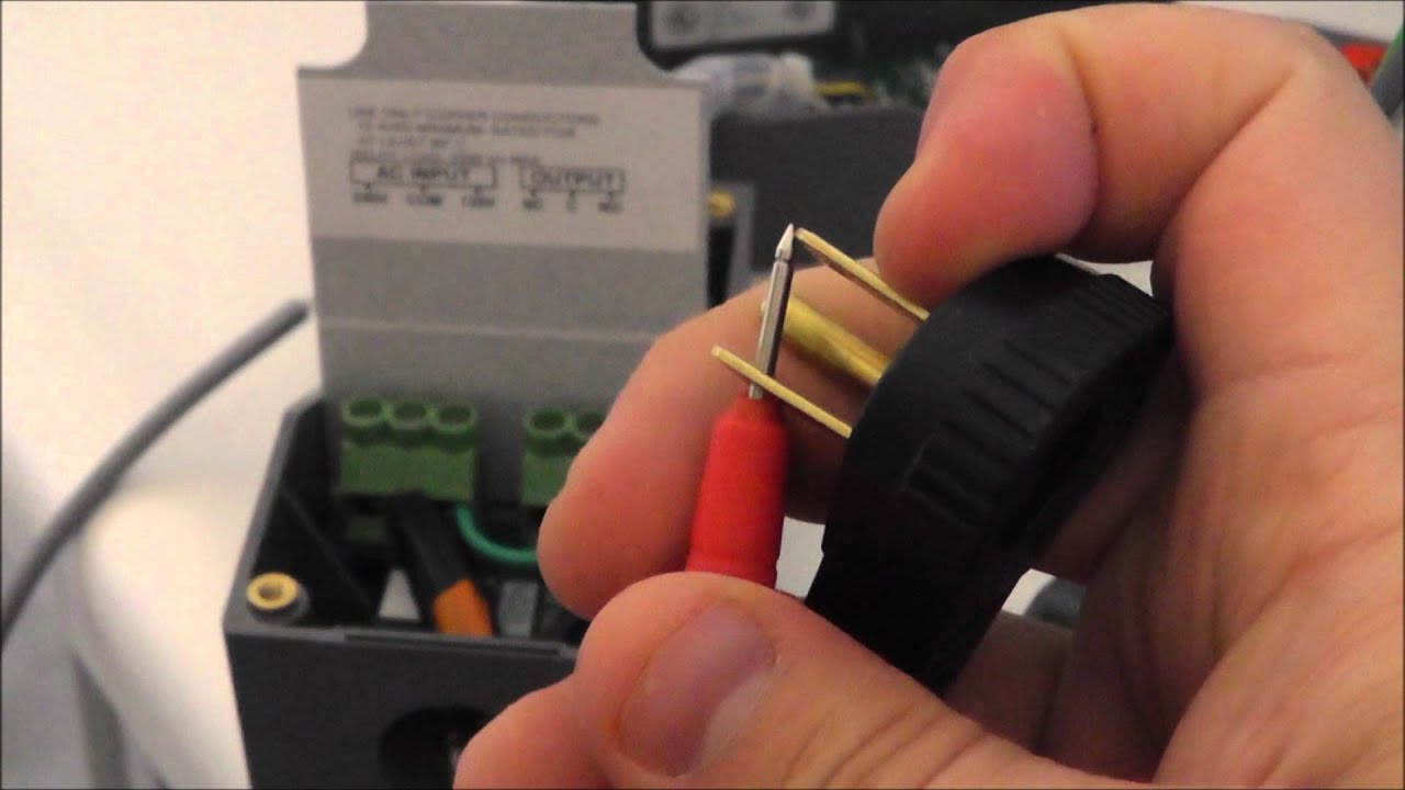
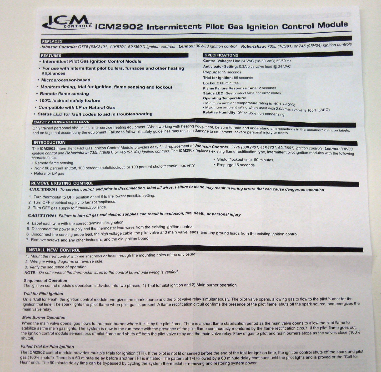
2 g600 series replacement intermittent pilot ignition controls installation instructions perform the following procedure to mount the new g600. Please verify your wiring before doing any work. The g600 may be.
Mastertech marine evinrude johnson outboard wiring diagrams with 1998 evinrude wiring diagram by admin through the thousand photos on line concerning 1998 evinrude wiring diagram picks the top series along with greatest resolution exclusively for you and this pictures is actually among photographs selections in this very best graphics gallery regarding 1998 evinrude wiring diagram. All wiring should be in. G g77x intermittent pilot ignition controls technical bulletin 9 flame sensor thermostat vent damper system transformer plug 5 24 v led ths 2 pv 1 mv 3 sense 4.
The voltage drop depends on the current draw wire gauge and wire length.


0 comments:
Post a Comment