Above we have describes the main types of trailer wiring diagrams. 12 n 7 pin wiring diagram.
The below information is for reference and is commonly used throughout the industry but can vary depending on who built the trailer.
You can find out more Diagram below
Towing wiring diagram. Need to know which color wire go to which post. How to install trailer wiring on your vehicle. 4 pin trailer wiring diagram.
2008 dodge ram 1500 trailer brake wiring diagram fresh dodge wiring. Electric trailer brake wiring schematic collections of electric trailer jack wiring diagram download. We have an excellent wiring diagram on our website i will provide you a link so you.
We recommend these standards because they are pretty universal. Any vehicle towing a trailer requires a trailer wiring harness to safely connect the taillights turn signals brake lights and other necessary electrical systems. Wiring diagrams an important aspect of towbar fitting is the wiring which is required to power either your trailer lights or caravan internal electrics.
Trailer connector wireing diagram. To connect the electric system of your trailer to the vehicle you will be using special connector. This is often overlooked when booking a towbar or can be difficult to understand exactly what your vehicle requires if you have none or very little knowledge.
Collection of ford 7 pin trailer wiring diagram. Wiring diagram for stock trailer refrence lovely trailer wiring. It reveals the components of the circuit as simplified forms as well as the power and also signal links in between the gadgets.
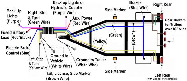
4 way flat molded connectors allow basic hookup for three lighting functions. Curt trailer brake controller wiring diagram control in wiring. When wiring a trailer connector it is best to wire by function as wire colors can vary.
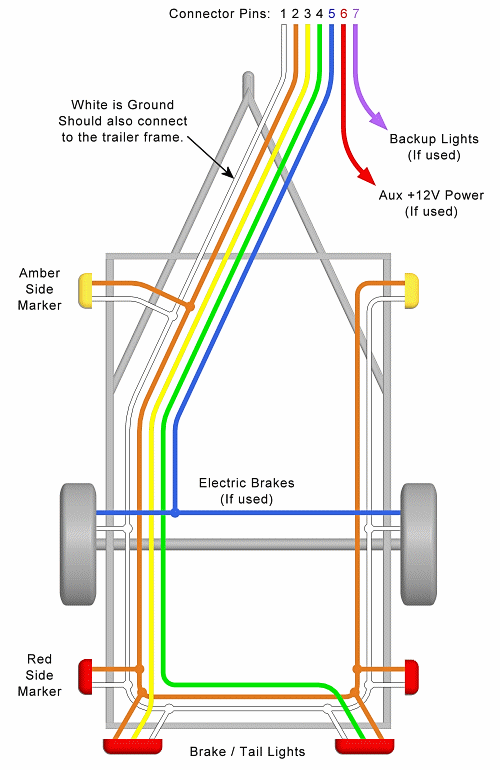
Various connectors are available from four to seven pins that allow for the transfer of power for the lighting as well as auxiliary functions such as an electric trailer brake controller backup lights or a 12v power supply for a winch or interior trailer lights. A wiring diagram is a streamlined traditional photographic depiction of an electrical circuit. Right turn signal stop light green left turn signal stop light yellow taillight license side marker brown and a ground white.
Below is the generic schematic of how the wiring goes. Trailer wiring diagrams 4 way systems. You can use a circuit tester to verify connections.
That said for specific situations there are industrial standards with different connectors and wire arrangements. 7 way rv trailer connector wiring diagram. The following trailer wiring diagrams and explanations are a cross between an electrical schematic and wiring on a trailer.
Check out or trailer wiring diagrams for a quick reference on trailer wiring.


0 comments:
Post a Comment