Remote control cars also known as rc cars are something every electronic hobbyists would love to build. Then comes the day when you would like to start racing competitively and you want get yourself a kit car that requires manual assembly that.
Take a look at how you make your power connections.

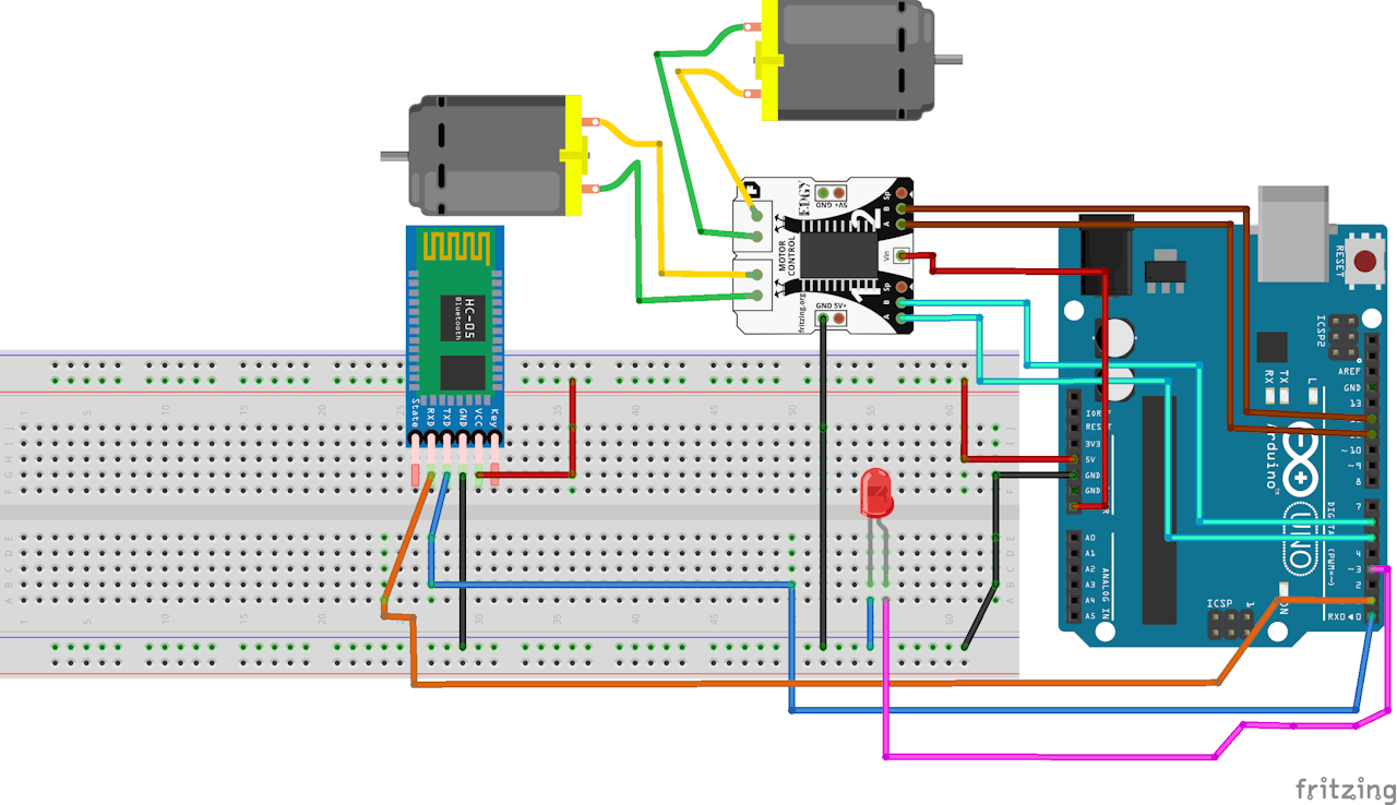
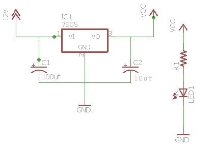
You can find out more Diagram below
Rc car wiring schematic. I was so happy if you get the article on our simple website. Turn that rats nest into a work of art. So many times we go to races and find competitive or at least semi serious racers using the stock length wiring because they are scared to cut it.
Rc car wiring welcome to our site this is images about rc car wiring posted by ella brouillard in rc category on oct 08 2019. Mount your gear so you have the least amount of wire. Since the day you started in rc your first cars have probably been ready to run vehicles for the ease of plug and play action.
We have so many collections wire wiring diagrams and schematics possibly including what is you need such as a discussion of the rc car circuit diagram pdf. The following is a high level block diagram showing the data path through the system. I have been searching the internet for a week to find a circuit schematic for a rc car.
Glad to help you and visit us back. It just needs to control 2 motors and have a range of maybe 30metres. Do not run the full length of wiring.
I dont want anything fancy the most basic of basic wiring diagrams will do. The complete guide to rc electronics. Next lets look at battery packs and plugs.
I have often found hobby rc electronics to be of interest in my projects due to their apparent simplicity and ease of use. Radio remote control car sending schematic diagram rc car circuit diagram pdf. This article is focused to guide hobbyists to build their own homemade rc car with.
You can also find other images like images wiring diagram images parts diagram images replacement parts images electrical diagram images repair manuals images engine diagram images engine scheme diagram images wiring harness diagram images fuse box diagram. These circuits were connected to the joystick to allow the microcontroller to read steering and speed input from it. Note that all these links are external and we cannot provide support on the circuits or offer any guarantees to their accuracy.
But most of them didnt know where to start and how to build it some even got deceived by its complex looks. I cant find a circuit schematic for any sort of rc car complex or simple so any help would be great thanks. Some circuits would be illegal to operate in most countries and others are dangerous to construct and should not be attempted by the inexperienced.
However it took me a while to figure out how to put together all the different components figure out w.


0 comments:
Post a Comment