If you use a bright light and look at the female connector ta4f used for the cable you will see numbers next to each hole. Mic wiring can be frustrating enough but when you cant find the right wiring info it is just impossible.
The pictorial shows the pin layout of a ta4f connector as viewed from the wiring side.
You can find out more Diagram below
Wiring diagram for condenser microphone. The list below offers some microphone wiring information. Microphone is not working properly and needs to be replaced you are likely to feel the burden of extra cost. Such as you now you are searching for fresh concepts regarding condenser microphone schematic diagram right.
Looking for fresh concepts is among the most exciting actions but it can be also annoyed whenever we can not find the desired ideas. Connect audio lead black to pins 3 and 4. Other related microphone wiring information.
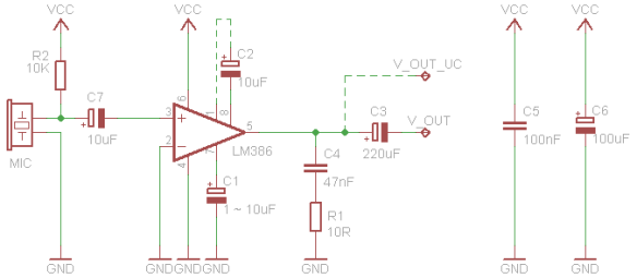
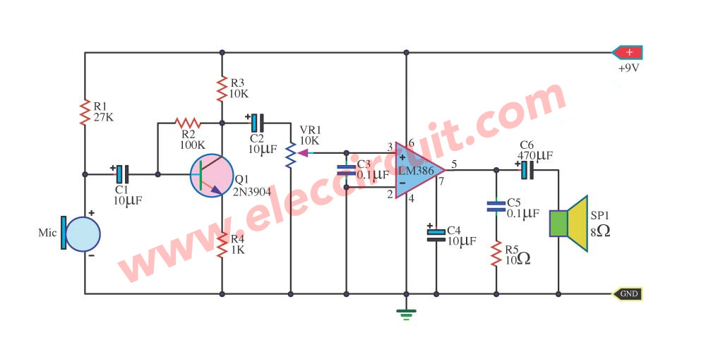
The chart and image above are correct for these models. It compose the importance is part pre mic use transistor just one enlarge sound signal gives the power goes up change come to a part amplifier with the integrated circuit lm386 utter go out give a loudspeaker. Links to microphone wiring diagrams is a curation of 29 resources about electro voice 664 wiring kenwood pin connectors microphone connections by g4wpw kenwood mc 50 modification kenwood tr 7950 microphone pinout.
The stereo socket takes condenser microphone as input and provides the. All sound cards and modems have a socket for microphone that is in compatible with stereo jack pins. Black wire serves as ground just like in every other apparatus.
The red one is to get positive cable with dc power of 5 volts. This circuit be signal sound expansion from condenser microphone give with small sized loudspeaker. We will continue to try to get all the information that we can listed on this page.
Radio mic wiring diagram. Here is a low cost microphone circuit that comes within your budget. Condenser microphones shure wh30 pg30 wl18x wl50 wl51 wl93 etc.
According to wiring color diagram on a usb microphone there are just four wires used inside the cabletypically it uses black black red and white cable colours. Many types of microphones require power to operate as a general rule these types are described as condenser microphones. The power is used for internal pre amplifiers and polarizing microphone capsules.
Resources listed under mic wiring category belongs to technical reference main collection and get reviewed and rated by amateur radio operators.


0 comments:
Post a Comment